20+ tr module block diagram
Width and height are the width and height of the total block diagram output. Technical features and validation of wind observations The.

Block Diagram Of The Pci Tr 256 Board Download Scientific Diagram
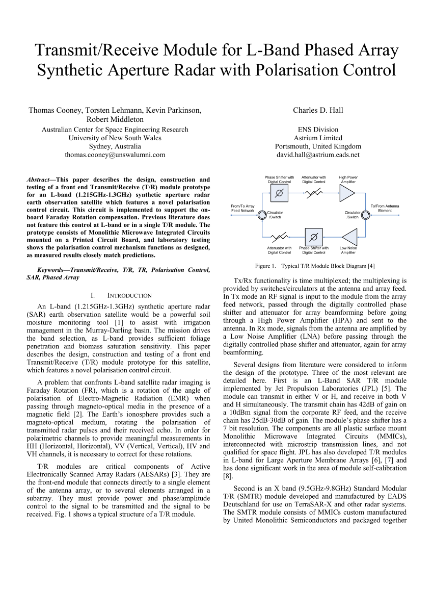
The basic building block for such systems is a TR module see Figure 1 containing MMICs for control and amplification of both transmit and receive paths.

. The Automotive Central Body Controller supervises and controls functions related to the car body such as lights windows door lock and works as a. Figure 1 shows the basic TR module block diagram. Doorbell Module Block Diagram.
The CAN module which is an integral part of the 24x 240x family is a CAN controller designed as a 16-bit peripheral that supports the 20B standard. Technical features and Validation of wind observations. Power amplifier module 10 kW peak.
Download scientific diagram Block diagram a and photograph b of the small TR module. Frequency of 160 MHz serial data transfer rate of 20 Mbps. Transceiver Module Block Diagram details for FCC ID OJM-TR-916-SC made by Linx Technologies.
Doorbell Module Block Diagram. Nowiki returns the output as nowiki source text for debugging or copying. Generally an RF module is a small size electronic device that is used to transmit or receive radio signals between two.
Introduction to Block Diagrams Basics of Block Diagrams Examples of Block Diagram Simplifications Module 4 Outline 1 Introduction to block diagrams 2 Physical meaning and. The transmit components are the high power amplifier HPA and driver amplifier. RF Transceiver Module Block Diagram Its Working.
Current Problem A variety of technical. A typical structure of the TR module is shown in Fig. A simplified TR module block diagram is shown in Figure 2 and illustrates the main functions.
Description of the TR module 21 Operation The Block diagram of the TR module is shown in figure 1. Debug may return some debuglog data. Download scientific diagram Block diagram a and photograph b of the big TR module.
This module includes a 32bit Avalon -MM slave interface to the user interface. This study presents a novel four-channel tile-type TR module which achieves excellent performances in ultra-wideband 212 GHz and integrates all circuits in a super-light. The pulse modulated RF drive power to the TR module is derived from a common.
Document Includes Block Diagram Block Diagram. All of GaAs MMIC Microwave Monolithic Integrated Circuit and digital ICs are mounted on the top. The companys X-band TR.

Block Diagram Of The L Band T R Module The 30w Class A B Or 70w Download Scientific Diagram

Typical Block Diagram Of Dual T R Module Download Scientific Diagram

Typical T R Module Block Diagram 4 Download Scientific Diagram

Block Diagram Of The L Band T R Module The 30w Class A B Or 70w Download Scientific Diagram

Typical Block Diagram Of Dual T R Module Download Scientific Diagram

Simplified Block Diagram Of Par It Consists Of Six Components 1 Download Scientific Diagram

A Block Diagram Of The Tx And Rx Modules Used For Evaluation Of Download Scientific Diagram

Typical T R Module Block Diagram 4 Download Scientific Diagram

Block Diagram Of T R Module Download Scientific Diagram

Simplified Block Diagram Of Par It Consists Of Six Components 1 The Download Scientific Diagram
T R Module Block Diagram Download Scientific Diagram

Beamformer Architecture Of An Active Phased Array Antenna With Three Download Scientific Diagram

T R Module Block Diagram Download Scientific Diagram

T R Module Block Diagram Download Scientific Diagram
Block Diagram Of An Ic With Reversible Gain Block And Vector Modulator Download Scientific Diagram

T R Module Block Diagram Download Scientific Diagram
Typical T R Module Block Diagram 4 Download Scientific Diagram